To achieve the air flow rates specified by the manufacturer, several points must be considered when planning the exhaust air duct.
It should be noted that different individual resistances occur in round pipes, hoses, flat ducts, deflector pieces, and reducers depending on their design. These add up and lead to a reduction in air flow rate and an increase in operating noise. Therefore, it is recommended to plan the duct as short, straight, and without reducers as possible, and to include the position and design of the exhaust duct when determining the air flow rate.
The exhaust connections of common range hoods are round and have diameters of 100, 125, 150, 180, 200 mm (though 100 mm diameters are now rare). Some manufacturers offer so-called stepped connectors, which allow exhaust ducts with different diameters to be connected as needed. However, whenever possible, the largest possible diameter should be chosen and maintained throughout the entire exhaust duct.
A smaller duct diameter leads to higher back pressures, which in turn lead to reduced hood air performance and increased noise generation. Manufacturer recommendations for the combination of exhaust duct and air flow rate:
- Ø 100 mm up to 300 m3/h
- Ø 125 mm up to 500 m3/h
- Ø 150 mm up to 800 m3/h
- Ø 200 mm up to 1800 m3/h
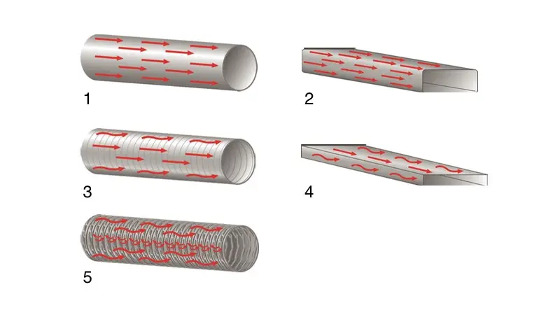
Overview of Exhaust Air Ducts
Round Pipe
Smooth round pipes are optimal for air flow. They do not change under temperature influence and should therefore be used if the structural conditions allow.
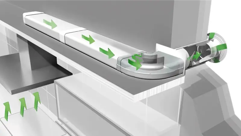
Flat Duct
A flat duct has the same smooth inner surface as a round pipe. The higher the flat duct, the more favorable it is for air flow. However, the round outlet connector on the range hood must be changed to the rectangular flat duct. This causes turbulence in the transition piece. The same occurs at the wall box, which is again round. When using a flat duct, care must be taken to maintain the cross-section of the exhaust connector as consistently as possible up to the wall box. Flat ducts that do not have an equivalent cross-sectional area should not be used because they lead to losses in air flow rate and increased noise generation. For design reasons, flat ducts are often preferred over round pipes. Through the use of air guide plates in the deflector pieces of flat ducts, flow characteristics are now achieved that sometimes exceed those of round pipes.
Flexible Aluminum Pipes
The flexible aluminum pipe is length-stable and flame-retardant. Aluminum flex pipes with low wave height (3-4 mm) cause significantly less turbulence/pressure loss than, for example, extremely compressible formed pipes and hoses. They are expandable and flexible and adapt to structural conditions.
Plastic Spiral Hose
The plastic hose is reinforced with a metal spiral. This hose is flexible and comfortable for installers to work with, as it can be continuously laid around all corners and obstacles. However, the relatively large waves inside the hose lead to strong turbulence in the airflow, resulting in performance losses and increased noise pollution. Additionally, the hose film can warm up and expand due to the exhaust air, leading to unevenness and additional air flow turbulence.
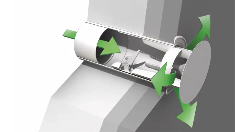
Deflectors and Reducers
At reduction and deflection pieces, turbulence and backflow occur, which additionally increase back pressure and noise development while reducing the efficiency of the exhaust hood.
The use of at least one deflector is usually unavoidable. In principle, however, reductions and deflectors should be minimized, and sharp angles should be avoided. For example, using two bends with large radii (> 90°) allows for significantly lower-loss exhaust air guidance than a single 90° bend.
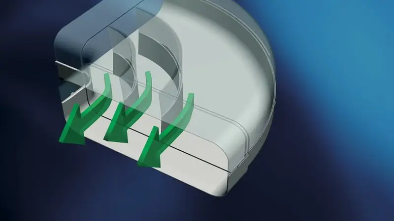
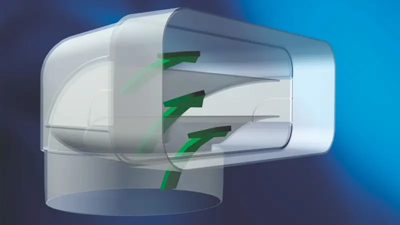
When deflectors with guide body technology are used, the exhaust air flows are specifically guided, smoothed, and directed with very low pressure losses. (Naber) Flat ducts with this guide body technology can sometimes transport exhaust air more effectively than round pipes without guide body technology.
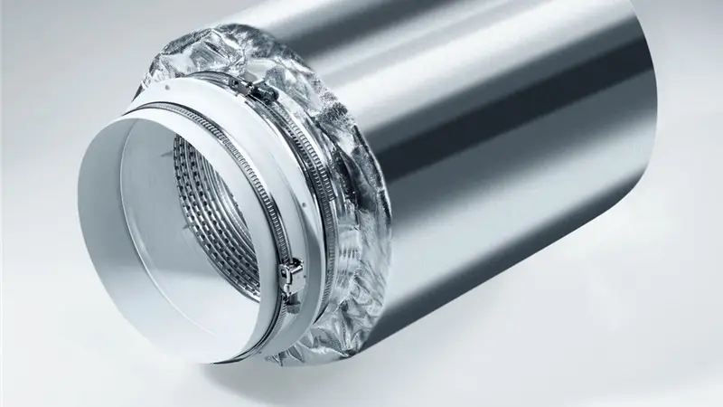
Sound Dampers
Installing a sound damper is useful for overall noise reduction. Depending on the manufacturer, this is offered for both exhaust and recirculation operation. In exhaust operation, both the fan noise to the outside and external noise entering through the exhaust duct can be dampened. In recirculation mode, the sound damper is placed directly on the fan connector in the hood chimney.
Condensation Formation
When warm cooking vapors are directed outside through the exhaust duct, they cool down (especially during cold seasons) at the transition point from warm to cold, and the moisture contained in the vapor can condense in the duct. To minimize condensation formation, installing a backdraft damper at the end of the exhaust path is recommended. To prevent condensate from flowing back to the hood, horizontal exhaust ducts should be installed with a 1-2° slope towards the outlet.
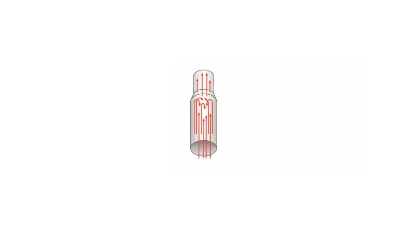
For vertically installed exhaust ducts (e.g., through a cold attic), insulation of the exhaust duct and a condensate separator are recommended. In the condensate separator, the precipitating water is caught in an overflow edge where it can evaporate. A condensate separator should be mounted directly above the exhaust outlet of the hood.
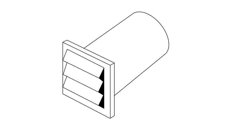
Wall Vents
For connections through exterior walls, a wall vent is used. Most wall vents are made of plastic or stainless steel and have fixed or movable louvers on the exterior side. Wall vents are typically telescopic to accommodate different wall thicknesses. To minimize condensation formation and prevent backflow, wall vents with non-return flaps are recommended. When conditions allow, the wall vent should be installed on the house wall facing away from the weather side.
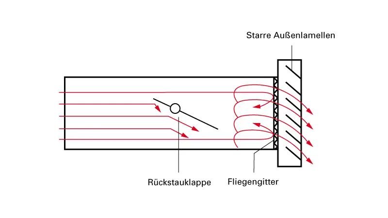
Common are pure exhaust wall vents with non-return flaps and fixed or movable louvers: With fixed louvers, the exhaust air is deflected immediately before exit. If the openings are not large enough, this can lead to turbulence, back pressure and increased noise generation. Wall vents with smooth-running louvers are designed so that the louvers open during exhaust. Under certain circumstances, they can also be moved by wind, which can lead to disturbing rattling.
Wall ducts with insect screens should never be used, as the fine mesh will clog over time, leading to major performance loss and excessive strain on the hood.
Motorized Wall Vents
Motorized wall vents are active vents that feature air or remote control. With remote control, the wall vent is connected to the range hood via a control cable and opens as soon as the range hood’s fan is switched on.
An air-controlled wall vent receives the signal to open when overpressure builds in the exhaust duct due to the range hood being turned on or vapor being extracted. Since this wall vent doesn’t require a control cable connection to the range hood, it can be combined with range hoods from different manufacturers. Motorized wall vents open and close the exhaust duct either via a round plug with internal drive unit or via a flap located on the exterior of the wall vent. All motorized wall vents require power supply. They are typically draft-proof, thermally and acoustically insulated, and can also be retrofitted to existing exhaust systems. Additionally, these wall vents have a larger exhaust opening without flow-deflecting louvers, resulting in significantly lower pressure losses.
From an energy perspective, motorized wall vents with insulation value specifications and blower door certification are particularly recommended. The blower door test verifies a house’s air tightness. For this test, a ventilator creates negative pressure in the house. Special measuring devices check if air flows into the building through leaks in the building envelope. If a ventilation system is to be installed in the house, according to energy saving regulations, the air exchange rate at test pressure must not exceed 1.5 times per hour. For passive houses, the value is below 1 time per hour. A blower door wall vent meets these airtightness requirements when closed. It opens as described above when triggered by the range hood and keeps the exhaust cover sealed with permanent magnets when not in use.
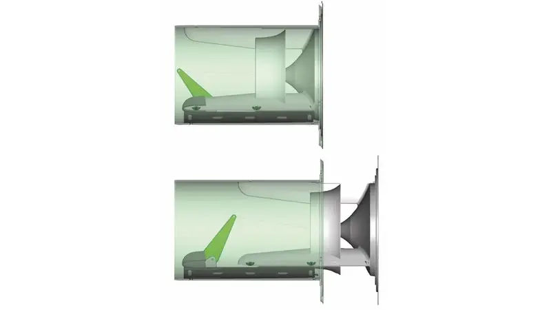
Exhaust/Supply Air Wall Vents
Besides pure exhaust and supply air wall vents, there are combined wall vents in single or dual-part designs. In both types, the openings for exhaust and supply air are arranged side by side or one above the other. The exhaust flap opens due to the outward flowing vapor. In single-part wall vents with one flap, the supply air flap automatically opens when exhaust air flows out. Dual-part wall vents open the supply air opening when negative pressure develops in the room. Mixing of exhaust and supply air is prevented by design.
The ideal solution for a supply/exhaust air system is two motorized wall vents with blower door certification: Supply and exhaust wall vents are electrically connected to each other and to the hood. Thus, they open and close simultaneously when the hood is turned on or off. This variant can be further improved with a supply air element with heat exchanger. These have an integrated heating coil that warms the incoming fresh air.
If a room-air-dependent heating system is present, an authorized chimney sweep must verify whether the amount of supply air introduced through the wall vent is sufficient to comply with fire safety regulations.
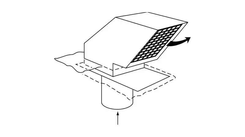
Roof Ventilation
To direct exhaust air outside through the roof, different roof ducts are available for various roof types. Since the attic and roof have significantly lower temperatures than the kitchen area, especially during cold months, the exhaust duct in this area needs to be insulated. Additionally, a condensation trap should be installed, particularly for vertically laid ducts. In the condensation separator, the condensed water is collected in an overflow edge where it can evaporate. A condensation separator should be mounted directly above the exhaust port of the range hood.
Performance Calculation of an Exhaust Hood Considering Pipe Resistance (Example Calculation)
Under point 5.3, an example calculation for air flow rate is shown, which only considers room volume and air exchange rate as the basis for determining hood performance. However, this doesn’t account for resistance created by the connected pipe system that accordingly reduces hood performance.
Since pressure losses in an exhaust duct depend on the material of individual components and air flow velocity, manufacturers cannot provide standardized resistance values for exhaust ducts.
For precise calculations, performance according to DIN EN 61591 must be known as input power into the exhaust system. With this performance, pressure losses of subsequent components can be determined individually. These are added and can then be transferred to the hood’s performance curves. Since a range hood operates with different volume flows and the friction resistance of the exhaust duct increases disproportionately with flow velocities, separate calculations must be made for each operating level.
If less than 50% of the “free-blowing” maximum performance remains after calculating the air system, a more favorable air routing must be pursued. This means larger diameters, shorter distances, fewer bends, or a blower unit instead of the integrated fan.
Some manufacturers offer customers individual calculations for selected hoods with required pipe parameters (Gutmann), or provide online planning tools that calculate whether the intended ventilation system is recommended (Gaggenau).
The diagram on page 2 of the PDF shows three performance curves of an exhaust hood: first power level, highest level, and intensive level. It shows the flow volume (m³/h) relative to back pressure (Pa). The intersections of the curves with the x-axis describe the flow volumes of individual power levels without back pressure (0 Pa) at the hood outlet (free-blowing). When the hood is fitted with an exhaust duct, back pressure increases and air flow performance decreases.
Four resistance curves of exhaust systems are shown in the diagram:
Pipe System (black curve):
This describes the resistance of the selected system and is thus the most important curve.
DIN/EN Values (yellow, light brown and brown curves):
These refer to a standard pipe section and represent comparison of different nominal widths:
- DIN/EN (5 PA) corresponds to NW 150
- DIN/EN (15 PA) corresponds to NW 125
- DIN/EN (30 PA) corresponds to NW 100
The diagram illustrates the significantly higher back pressure and associated lower flow performance of the hood with decreasing duct cross-section. The curve intersections correspond to the numerical values in the calculated table (1-5). Point 6 can be found in the hood’s technical data. The higher this maximum back pressure, the more powerful the hood is even with unfavorable piping.